-

Hi Leo,
Thanks a lot for your translation! Today just a short one: CI for D/A-Converter:
Allmost all DACs are based on several current sources 电源 [電源] diànyuán , that are turned on or off. The most significant Bit (MSB) switches the highest current source, the second Bit switches a current source with half the current of the former one, the third Bit switches half the current of the second one, means one forth of the MSB, and every following bit switches a current source that has half of the current compared to the former one. And this for 16 Bit, 24 Bit or 32 Bit (the most common DACs are 16, 24 or 32 Bit). (See picture DAC-CI)
今天要介紹是CI技術在D/A轉換的應用,大部份的DAC以許多電流來源 (電源) 為基礎,電源不是開就是關。最重要的Bit (MSB,most significant Bit) 轉換最高的電流來源,其次的Bit則是只有轉換前面電流的1半、第3個Bit又是只有第2個的1半,也就是只有第1個的1/4,接下來的每個Bit都是依此原則轉換,大部份的DAC大都是16Bit、24Bit、32Bit。
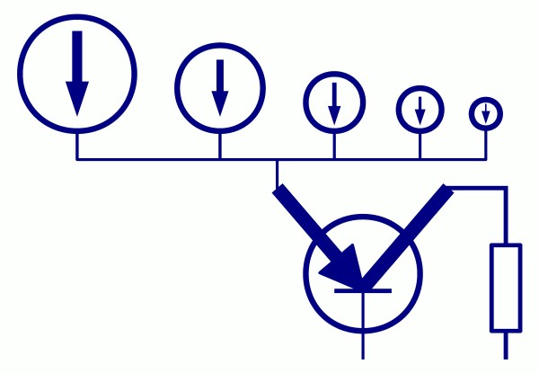
Now these current sources are connected to a CI-circuit, feeding the sum of the switched currents to E of the transistor. At the output the voltage is set by the resistor. At this point there is the output voltage of the DAC, without making a copy. That's it about CI for DAC.
現在這些電流連接到CI線路,提供了全部轉換的電流總合給電晶體E,因此輸出電壓是由電阻決定,在這點這是DAC的輸出電壓,而不需要經過COPY,就這就CI技術在DAC的應用。
Best regards,
Michael


-
-
DAC-CI versus OP-AMP
Hi Leo,
Thanks for your translation again!
Drunkenlife made a nice addition, showing the usual way of I/V conversion by an OP-Amp. Yes, over 99.9% of all D/A-converters use this approach, feeding the DAC current into the negative feedback-loop of an OP-AMP. And the example shown by drunkenlife is for sure one of the better OP-AMP solutions, having only one OP-AMP in each line. Most times there are even more.
感謝你的翻譯,Drunkenlife做了很好的補充,顯示了一般使用OP-AMP進行I/V轉換。是的,有99.9%的DAC都使用這樣的方式,提供DAC店流到OP-AMP的負迴授。drunkenlife所舉例的是其中一個OP-AMP不錯的方案,每一個線路只有一個OP-AMP,一般來說會有更多。
We have a different approach, and we have it for a reason. We don't like overall feedback loops in the audio range. We don't like making COPIES. And OP-AMP-ICs have a limited bandwidth, causing distortions, especially with the unfiltered high frequency trash of the digital domain. From our point of view OP-AMPs can not handle this task without creating distortions. We are sure the frequent complaint of digital sound is the
complaint about the sound of a "tortured" OP-AMP.
B.M.C 有不同的方法,我們不喜歡在聲音的範圍有整體回授,我們不喜歡COPY,OP-AMP-ICs的頻寬有限,會造成失真,特別是數位未經濾波的高頻。我們認為OP-AMPs無法解決這問題而沒有造成失真。我們確定一般抱怨的數位聲就是這裡所產生的。
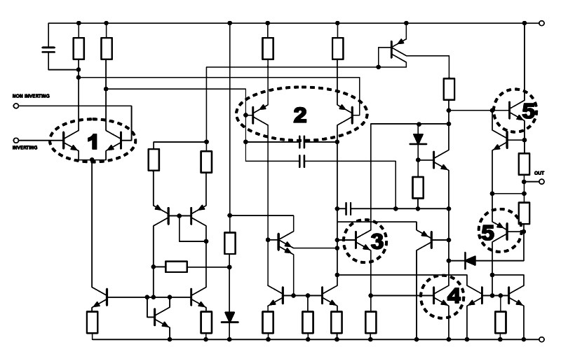
As I explained in post #25, we prefer avoiding copies by using our CI circuit. Attached is a schematic of one of the most used OP-AMP-ICs, the 5532. I have marked all the copy stages. You can see there are 5 copies done with this IC, means at the output you get a copy of a copy of a copy of a copy of a copy of the original input signal - just with one IC. Most circuits use several ICs in series.
在這篇編號#25中我有解釋,我們偏好在我們的CI線路中不要COPY(訊號),這張圖是最常用的OP-AMP-IC之一,5532,我標記了所有的COPY級,你可以看到這個IC有5個COPY地方,意味著在輸出時,你得到的是a copy of a copy of a copy of a copy of a copy of原來的訊號,且發生在只有一顆IC上,大部份的線路又使用了許多的IC。
OP-AMP-ICs only can be used with an overall negative feedback-loop, otherwise distortions and gain are too high and frequency response is decreasing a lot in the audio range. Due to the decreasing frequency response the phase is changed as well. All OP-AMP-ICs used for audio have a phase turned by 90?over most of the audio range. That is not ideal for a feedback-loop... I could go on with OP-AMP-IC-bashing some more pages... But just take it as our reason for a different circuit design without any need for overall negative feedback.
OP-AMP-ICs使能使用在整體負迴授,不然失真與增益會過高,頻率響應會在聲音範圍減少很多。由於頻率響應的減少,相位也會改變。對迴授這不是非常理想的方式。我可以說更多有關OP-AMP-IC-bashing,不過我只想說明這是為什麼B.M.C採用不同的線路設計,且不需要整體負迴授。
Thus we use a different approach, feeding the original current of the DAC chip into E (emitter) of the transistor and using this original current, until we define the output voltage with a resistor. At the output we still need a small LEF buffer for driving cables and following loads. But this means we make just one single copy.
因此我們用不同的方法,給DAC晶片原來的電流到電晶體的E(emitter),使用原來的電流,直到我們在電阻來確定輸出的電壓。在輸出我們依然需要LEF緩衝來驅動線材與阻抗。不過這意味我們只需一個單一的COPY。
Please keep in mind: Our shown circuits are kept simple for explanation.
Reality is more complex.
請記得這裡舉例是經過簡化的,主要為了解說方便,B.M.C的線路實際上是複雜很多的
Best Regards,
Michael
-
-
YES
Michael 說一般的作法是在Input Stage會Copy訊號.......然後進行放大 (如10倍?)
 作者: 查德

Source訊號不變,只調整Gain去做音量調整,避免訊號失真的方法~
-
-
這不是全部 (有些講完已經擦掉)
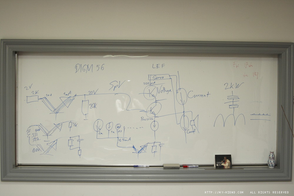
MY-HIEND的朋友
你們有認真在聽嗎?
(站長我是聽完霧煞煞啦...)

-
-
[QUOTE=小葉;132373]這不是全部 (有些講完已經擦掉)
MY-HIEND的朋友
你們有認真在聽嗎?
(站長我是聽完霧煞煞啦...)
有聽沒有懂8)8)
-
-
作者: kevintran
這個幾個圖好像只對綜擴有意義。
如果前後級分開,除了唱頭放大之外,其他的訊號在進後級前不是都是衰減嗎?
以DAC的高輸出而言,前後級加起來的gain實在太高了,沒啥必要吧...
作者: 小葉
也因為這樣的設計,他們的產品最好一套使用是最佳的
這項該是指current injection,
若是DAC的輸出電流量不夠(例如我改的DAC),那就不佳
以一般的DAC而言,都會有個buffer級,應該沒問題,BMC文件也提到這點
作者: 小葉
輸入級取的是電流,電壓放大級仍舊是固定gain(但有幾段可調),最後仍舊轉成電壓,以電壓驅動喇叭
這些與BMC不同
作者: 小葉
YES
Michael 說一般的作法是在Input Stage會Copy訊號.......然後進行放大 (如10倍?)
一般輸入級是組差動電路,取的是電壓
在這之前是音量衰減可變電阻,
之後是固定電壓放大倍率的電路
BMC的架構與此完全不同,
Accuphase的架構只改變了輸入級
作者: 小葉
輸入級以電流方式運作,一顆BJT就搞定了,
這架構若是搭上早期必須外掛I/V轉換的DAC IC,那,不就可以拿掉I/V轉換,更是簡潔...
突然看到設計者姓Conrad?與Conrad Johnson有關嗎?
-
The Following User Says Thank You to drunkenlife For This Useful Post:
-
Dear Leo,
Thanks a lot for your therad about BMC Audio! I can only read a little, and the google translation is not always correct... It is even harder to contribute something to your website, because my written Chinese is ZERO. But may be I can write to you by email, and step by step offer a little more information. As our technology is really new and unique, it is difficult to understand - even for people with a solid technical background. May be you can help me translating my comments to Chinese and publish them?
(以上翻譯略,就是Michael感謝MY-HIEND的報導,也希望我幫忙把他進一步解釋的部份翻成中文給大家,BMC的理論非常新與特別,就算是讀電子的可能也不太容易懂)
"Accuphase's AAVA circuit has nothing to do with our BMC design - much to complicated. AAVA has an input buffer, a V-I converter stage, a current addition and finally an I-V converter stage with a feedback loop and gain.
Accuphase AVVA的線路跟BMC不同,BMC複雜多了,AAVA有輸入緩衝,一個V-I轉換級,會增加電流,最終會有一個回授與增益的I-V轉換級。
To understand our approach it does not need to think that complicated.
瞭解BMC的方法不需要想得這麼複雜
CI input with DIGM volume control is a 1-stage amplification. The volume
control is just done with resistors (switched by transistors) at the output of this stage. After this gain adjustment there is no more voltage amplification. This means: The volume control happens at the voltage level of the speaker output.
使用DIGM音量控制的CI輸入是一級放大,音量控制是由輸出級的電阻(電晶體轉換)來處理,在這增益的調整後沒有任何電壓的放大,這意味著音量控制發生在喇叭輸出的電壓水平。
The only thing in common with the AAVA is: we have a potentiometer in the DAC1, a CPU reads out the position of the volume knob and translates it to a digital word, then this word is sent to the amplifier AMP S1 (or M1) by an optical connection. In the amplifier the digital word is used to activate some of the transistors of the DIGM to switch the required resistor (or combination of resistors).
與AAVA唯一相同的是,在B.M.C DAC1中,有個分壓計,CPU可以知道音量選鈕的位置將其變成數位語言,然後透過光纖將其發送到擴大機AMP S1 (或 M1)。在擴大機中,這些數位語言會啟動DIGM的電晶體來轉換成所需的電阻 (或將電阻組合)
It is a 1-stage design. The ouput of this stage is a current source. The gain is adjusted by the termination of this stage with a resistor, thus setting the I/V conversion."
這是一級的設計,在這級的輸出的來源是電流,增益是在這級最後由電阻來調整,就是I/V轉換
I hope this helps a little for a better understanding of DIGM.
I'll follow up with more explanations...
Best regards,
Michael
-
The Following 3 Users Say Thank You to Leo Yeh For This Useful Post:
-
最後那級與Devialet的概念有些類似,都是以伺服電路參酌電壓放大級以校正電流放大級
http://www.google.com/patents?id=g6X...page&q&f=false
CI, current injection這詞有趣...
定名者,說不定是車迷...彷缸內直噴吧...
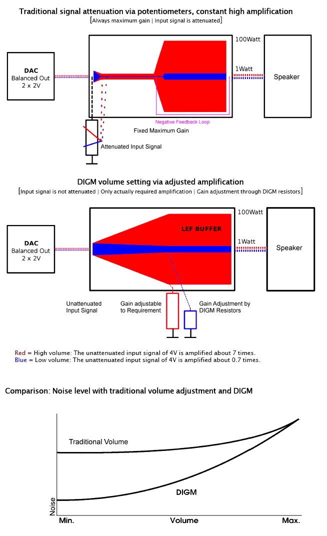
最下面這張圖的基本前提是擴大機內部總是會有某個程度的電源雜訊,
若輸入訊號一進擴大機就衰減,那麼訊號中的微弱變化量小於電源雜訊者,就會被雜訊蓋過去了...
這等效於放大雜訊的效應
因此才說,數位音量調整真的比擴大機內的VR衰減來的好嗎?難說...
-
The Following 2 Users Say Thank You to drunkenlife For This Useful Post:
-
這個幾個圖好像只對綜擴有意義。
如果前後級分開,除了唱頭放大之外,其他的訊號在進後級前不是都是衰減嗎?
-
-
沒有傳統前級的存在
Michael只提到input stage 與 output stage的處理方式
可看出目前B.M.C的產品沒有前級這一樣
http://www.bmc-audio.de/en/products.asp
也因為這樣的設計,他們的產品最好一套使用是最佳的
若有時間我會把錄音檔給放上來,大約40分鐘
其實我能理解的應該只有70~80%左右 (sweat)
前面的描述是我先就印象寫的
作者: kevintran
這個幾個圖好像只對綜擴有意義。
如果前後級分開,除了唱頭放大之外,其他的訊號在進後級前不是都是衰減嗎?
-
 發文規則
發文規則
- 您不可以發表新主題
- 您不可以發表回覆
- 您不可以上傳附件
- 您不可以編輯自己的文章
-
討論區規則
|